EMI Testing in Embedded Systems
EMI Testing in Embedded Systems: Why It Matters for Display-Driven Designs
When engineers integrate a TFT LCD display into an embedded product, most of the early effort goes into resolution, interface selection, backlight design, and touch integration. Electromagnetic interference (EMI) is often treated as a problem for the very end of the project—usually discovered the first time a prototype is taken to a compliance lab.
In practice, EMI is one of the most common reasons an otherwise finished embedded product fails certification and slips its schedule. Display modules are a frequent culprit: high-speed interface clocks, switching backlight drivers, and long flexible cables all radiate energy.
This article explains what EMI testing involves, which standards apply, why display-driven embedded systems are especially prone to EMI problems, and what engineers can do to pass compliance the first time.
EMI vs EMC: Clarifying the Terms
The two terms are related but not identical.
| Term | Meaning |
|---|---|
| EMI | Electromagnetic Interference — the unwanted energy a device emits or receives |
| EMC | Electromagnetic Compatibility — the device’s ability to coexist with its environment |
EMC is the overall goal. EMI testing is how that goal is verified. A product is considered electromagnetically compatible when it neither emits excessive interference nor malfunctions when interference is present.
EMC testing therefore splits into two broad questions:
- Emissions — How much noise does the product produce?
- Immunity (susceptibility) — How well does the product tolerate external disturbances?
A complete compliance campaign measures both.
Why Embedded Display Systems Are Prone to EMI
Embedded products with displays combine several strong noise sources in a small enclosure.
Common contributors include:
- High-speed serial interface clocks (MIPI-DSI, LVDS, parallel RGB)
- Backlight LED driver switching frequencies
- DC-DC converters and switching regulators
- Long flexible printed circuit (FPC) cables acting as antennas
- Fast digital edges on data lines
The display interface is often the dominant offender. The choice between MIPI, LVDS, and RGB directly affects emissions: parallel RGB exposes many switching lines, while differential pairs such as LVDS and MIPI confine more of their energy but still radiate if routing is poor.
The backlight driver circuit is a second major source. PWM dimming and boost converters generate broadband switching noise that couples into nearby traces and cables.
Finally, FPC layout and pin mapping matters more than many engineers expect. A poorly arranged flat cable—signals without adjacent ground returns—behaves like an efficient antenna across a wide frequency range.
Categories of EMI Testing
EMI testing is divided into four practical categories.
| Category | Type | Question Answered |
|---|---|---|
| Conducted emissions | Emissions | Noise leaving via power/signal cables |
| Radiated emissions | Emissions | Noise radiated through the air |
| Conducted immunity | Immunity | Tolerance to noise injected on cables |
| Radiated immunity | Immunity | Tolerance to external fields |
Most embedded products must pass all four to reach the market.
Conducted Emissions
Conducted emissions are interference signals that travel out of the product along its cables—most often the power input.
Typical characteristics:
- Frequency range commonly 150 kHz to 30 MHz
- Measured using a LISN (Line Impedance Stabilization Network)
- Strongly influenced by switching power supplies
Switching regulators and the backlight boost converter are usually the main contributors. Input filtering, decoupling, and careful ground design are the primary defenses.
Radiated Emissions
Radiated emissions are interference signals that leave the product through the air.
Typical characteristics:
- Frequency range commonly 30 MHz to 1 GHz (and higher for fast interfaces)
- Measured in a semi-anechoic chamber or open-area test site
- Strongly influenced by clock harmonics and cable behavior
Display interface clocks and their harmonics frequently appear as narrow spikes in the radiated spectrum. Because cables radiate efficiently, the FPC connecting the main board to the display is often where these emissions escape.
Common EMI Standards
Different markets and product classes apply different standards. The most frequently encountered are listed below.
| Standard | Scope |
|---|---|
| CISPR 32 / EN 55032 | Emissions for multimedia equipment |
| CISPR 11 / EN 55011 | Emissions for industrial, scientific, medical equipment |
| FCC Part 15 | Emissions limits for the US market |
| IEC 61000-4-2 | ESD immunity |
| IEC 61000-4-3 | Radiated field immunity |
| IEC 61000-4-4 | Electrical fast transient / burst |
| IEC 61000-4-5 | Surge immunity |
The exact standard depends on the product category and target region. Industrial and medical displays usually face stricter requirements than consumer devices.
Immunity Testing in Detail
Immunity testing verifies that the product keeps working—or recovers gracefully—when disturbed. For display systems, a common failure mode is a screen that flickers, freezes, or blanks during a disturbance.
1. Electrostatic Discharge (ESD)
ESD testing (IEC 61000-4-2) simulates the static discharge from a human touch.
- Applied to touch surfaces, connectors, and exposed metal
- Common levels: ±4 kV contact, ±8 kV air discharge
- Display and touch panels are frequent failure points
Capacitive touch panels are especially sensitive, so ESD protection on touch lines is essential.
2. Electrical Fast Transient (EFT / Burst)
EFT testing (IEC 61000-4-4) injects bursts of fast transients onto power and signal lines, simulating relay or switch noise common in industrial environments.
Effects on displays may include momentary flicker, image corruption, or controller reset.
3. Surge
Surge testing (IEC 61000-4-5) simulates high-energy events such as nearby lightning or power switching.
Power input protection—TVS diodes, varistors, and filtering—is the main defense.
4. Radiated Immunity
Radiated immunity testing (IEC 61000-4-3) exposes the product to strong external electromagnetic fields.
Sensitive display behaviors include:
- Backlight flicker
- Image distortion
- Touch instability
- Communication errors on the display interface
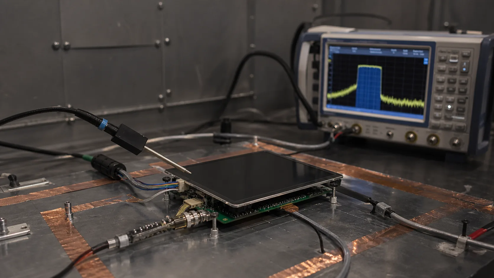
Pre-Compliance Testing
Booking a full accredited lab is expensive, and failures there are costly in both money and schedule. Many teams perform pre-compliance testing in-house first.
Typical pre-compliance tools include:
| Tool | Purpose |
|---|---|
| Spectrum analyzer | Measure emission frequencies and levels |
| Near-field probes | Locate noise sources on the PCB |
| LISN | Measure conducted emissions |
| ESD gun | Perform basic ESD checks |
Near-field probes are particularly useful for display work: sweeping the probe over the board and along the FPC quickly reveals whether the interface clock, the backlight driver, or the cable is the dominant emitter.
Pre-compliance results are not certifiable, but they dramatically reduce the risk of failing the formal test.
Common EMI Mitigation Techniques
When a display-driven product fails EMI testing, the fixes usually fall into a small set of categories.
Shielding
- Metal enclosures or shielding cans over noisy circuits
- Shielded FPC or coaxial cabling for high-speed interfaces
- Conductive gaskets to close enclosure gaps
Grounding and Return Paths
- Continuous ground planes beneath high-speed traces
- Adjacent ground returns for every signal in the FPC
- Short, low-impedance connections to chassis ground
Most display EMI problems trace back to a poor or interrupted return path.
Filtering and Decoupling
- Common-mode chokes and ferrite beads on cables
- Decoupling capacitors close to driver ICs
- Input filtering on power rails
Spread-Spectrum Clocking
Many display controllers and processors support spread-spectrum clocking (SSC), which spreads clock energy across a small frequency band instead of concentrating it at sharp harmonics.
SSC can reduce peak radiated emissions by several dB and is often the simplest single change that brings a clock harmonic below the limit.
Layout and Routing
- Keep high-speed traces short and impedance-controlled
- Avoid routing sensitive signals near switching regulators
- Maintain tight differential pair coupling for MIPI and LVDS
- Place the backlight driver away from the display interface
Good layout is the cheapest EMI fix because it costs nothing once the board is designed correctly. Understanding the basics of the underlying technology, as covered in What is TFT LCD, helps engineers anticipate where noise will originate.
Typical EMI Test Workflow
A simplified compliance process often looks like this:
| Step | Description |
|---|---|
| Pre-compliance scan | Identify dominant emitters in-house |
| Design fixes | Apply shielding, filtering, layout changes |
| Verify improvement | Re-measure with near-field probes |
| Formal emissions test | Conducted and radiated at accredited lab |
| Immunity testing | ESD, EFT, surge, radiated immunity |
| Documentation | Record results for certification |
Catching problems in the pre-compliance stage is far cheaper than discovering them at the accredited lab.
Why EMI Testing Is Becoming More Important
As embedded products add larger, brighter, and faster displays, EMI challenges are increasing.
Several trends drive this:
- Higher interface data rates and faster edges
- Brighter backlights with more powerful drivers
- Denser enclosures with less room for shielding
- Stricter regulatory requirements in industrial and medical markets
- More wireless functions sharing the same enclosure
In many projects, EMI performance now influences schematic, layout, and mechanical decisions from the very start.
Conclusion
EMI testing is often treated as a final checkbox before shipping, but for display-driven embedded systems it deserves attention from the beginning of the design.
Display modules combine several of the strongest noise sources in a typical product: high-speed interface clocks, switching backlight drivers, and long flexible cables. Without early planning, these almost guarantee a difficult compliance phase.
By understanding the difference between emissions and immunity, applying the relevant standards, using pre-compliance testing to locate problems early, and following sound shielding, grounding, filtering, and layout practices, engineers can dramatically improve their chances of passing EMI testing the first time—and avoid the costly redesign cycles that EMI failures so often cause.